This site is from a past semester! The current version will be here when the new semester starts.

Week 8 [Fri, Mar 3rd] - Topics

Detailed Table of Contents


Guidance for the item(s) below:


[image source]

In an earlier week you learned how to interpret class diagrams and object diagrams. Let's go back to that topic but this time let's learn how to draw those diagrams to match code. You'll need to draw class/object diagrams when you document the design of your tP.

But note that while in the tP you'll be using diagramming tools to draw the diagram, here, we focus on hand drawing. The reason is, we also want you to be able to quickly hand-draw UML diagrams to aid discussions (e.g., draw a diagram on a whiteboard while explaining a design decision to colleagues).

The relevant UML topics are repeated further down in this page, for reference. In addition, here are some worked-examples/exercise of drawing class/object/sequence diagrams:

Video Q+ Drawing class/object diagrams (basic) - Box, Item, Lid

Video Drawing class/object diagrams (intermediate) - Action, Task, History

Video Drawing class/object diagrams (intermediate) - Person, Inbox, Message

Video Drawing class/object diagrams (intermediate) - Person, Project, Task

Video Drawing sequence diagrams (basic) - Item creation

Video Drawing sequence diagrams (intermediate) - TaskList#generateTask()

Video Drawing sequence diagrams (intermediate) - create Quote

[W8.1] [Revisiting] Drawing Class/Object Diagrams - Basics

Video

W8.1a

Design → Modelling → Modelling Structure → Class diagrams - basic

Can use basic-level class diagrams

Contents of the panels given below belong to a different chapter; they have been embedded here for convenience and are collapsed by default to avoid content duplication in the printed version.

UML Class Diagrams → Introduction → What


Classes form the basis of class diagrams.

UML Class Diagrams → Classes → What


UML Class Diagrams → Class-Level Members → What


Associations are the main connections among the classes in a class diagram.

OOP Associations → What


UML Class Diagrams → Associations → What


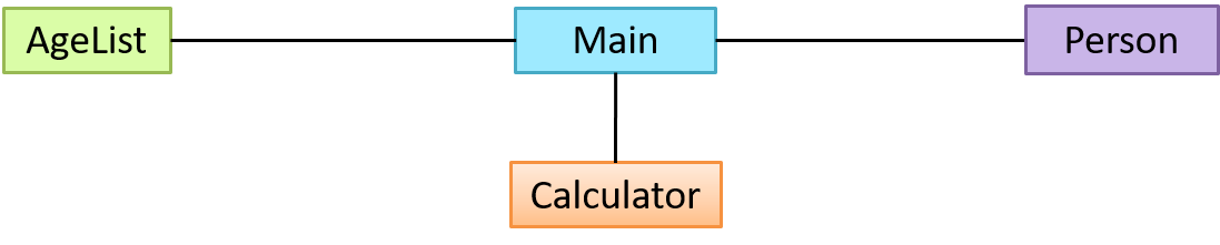
The most basic class diagram is a bunch of classes with some solid lines among them to represent associations, such as this one.

An example class diagram showing associations between classes.

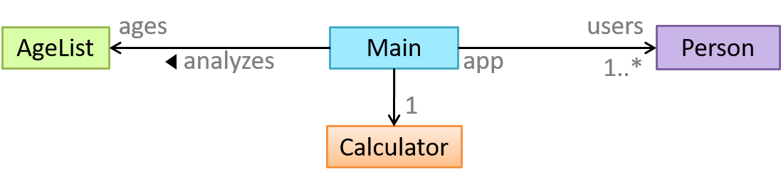
In addition, associations can show additional decorations such as association labels, association roles, multiplicity and navigability to add more information to a class diagram.

UML Class Diagrams → Associations → Labels


UML Class Diagrams → Associations → Roles


OOP Associations → Multiplicity


UML Class Diagrams → Associations → Multiplicity


OOP Associations → Navigability


UML Class Diagrams → Associations → Navigability


Here is the same class diagram shown earlier but with some additional information included:

Exercises

Which association notations are shown?


Explain Class Diagram


Draw Class Diagram for Box etc.


W8.1b

Design → Modelling → Modelling Structure → Object diagrams

Can use basic object diagrams

UML → Object Diagrams → Introduction


Object diagrams can be used to complement class diagrams. For example, you can use object diagrams to model different object structures that can result from a design represented by a given class diagram.

UML → Object Diagrams → Objects


UML → Object Diagrams → Associations


Exercises

Draw an Object Diagram for Box etc.


W8.1c

Tools → UML → Object versus class diagrams

Can distinguish between class diagrams and object diagrams

Compared to the notation for class diagrams, object diagrams differ in the following ways:

  • Show objects instead of classes:
    • Instance name may be shown
    • There is a : before the class name
    • Instance and class names are underlined
  • Methods are omitted
  • Multiplicities are omitted. Reason: an association line in an object diagram represents a connection to exactly one object (i.e., the multiplicity is always 1).

Furthermore, multiple object diagrams can correspond to a single class diagram.

Both object diagrams are derived from the same class diagram shown earlier. In other words, each of these object diagrams shows ‘an instance of’ the same class diagram.

When the class diagram has an inheritance relationship, the object diagram should show either an object of the parent class or the child class, but not both.

Suppose Employee is a child class of the Person class. The class diagram will be as follows:

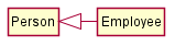
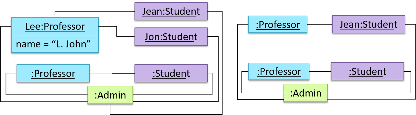
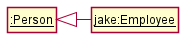
Now, how do you show an Employee object named jake?

  • This is not correct, as there should be only one object.
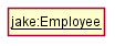
  • This is OK.

  • This is OK, as jake is a Person too. That is, we can show the parent class instead of the child class if the child class doesn't matter to the purpose of the diagram (i.e., the reader of this diagram will not need to know that jake is in fact an Employee).

Association labels/roles can be omitted unless they add value (e.g., showing them is useful if there are multiple associations between the two classes in concern -- otherwise you wouldn't know which association the object diagram is showing)

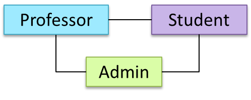
Consider this class diagram and the object diagram:

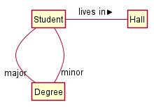
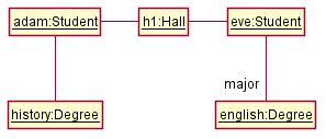
We can clearly see that both Adam and Eve lives in hall h1 (i.e., OK to omit the association label lives in) but we can't see if History is Adam's major or his minor (i.e., the diagram should have included either an association label or a role there). In contrast, we can see Eve is an English major.

Exercises


[W8.2] [Revisiting] Drawing Class/Object Diagrams - Intermediate

Video

W8.2a

Tools → UML → Notes

Can use UML notes

UML notes can augment UML diagrams with additional information. These notes can be shown connected to a particular element in the diagram or can be shown without a connection. The diagram below shows examples of both.

Example:


W8.2b : OPTIONAL

Tools → UML → Constraints


W8.2c

Tools → UML → Class Diagrams → Associations as attributes

Can show an association as an attribute

An association can be shown as an attribute instead of a line.

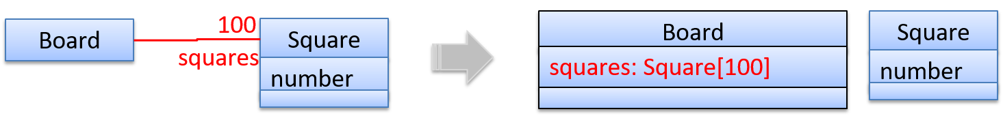
Association multiplicities and the default value can be shown as part of the attribute using the following notation. Both are optional.

name: type [multiplicity] = default value

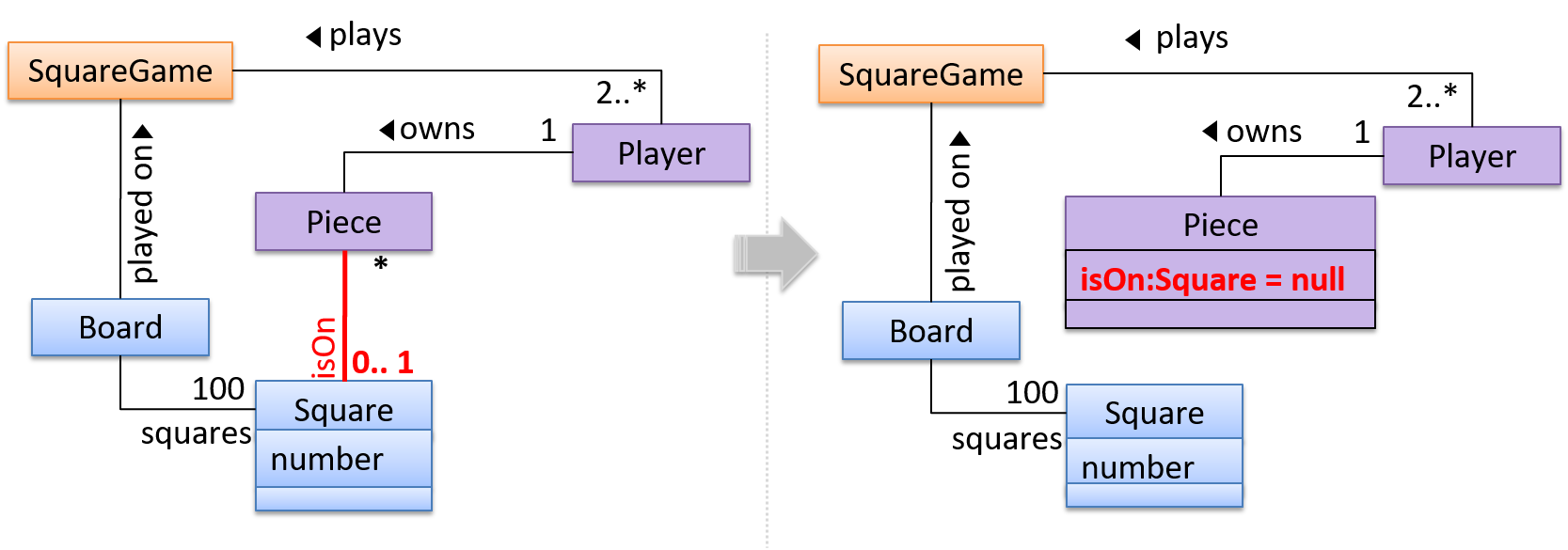
The diagram below depicts a multi-player Square Game being played on a board comprising of 100 squares. Each of the squares may be occupied with any number of pieces, each belonging to a certain player.

A Piece may or may not be on a Square. Note how that association can be replaced by an isOn attribute of the Piece class. The isOn attribute can either be null or hold a reference to a Square object, matching the 0..1 multiplicity of the association it replaces. The default value is null.

The association that a Board has 100 Squares can be shown in either of these two ways:

Show each association as either an attribute or a line but not both. A line is preferred as it is easier to spot.


W8.2d

Design → Modelling → Modelling Structure → Class diagrams - intermediate

Design → Modeling → Class Diagrams (Basic)


Can use intermediate-level class diagrams

A class diagram can also show different types of relationships between classes: inheritance, compositions, aggregations, dependencies.

Modeling inheritance

OOP → Inheritance → What


UML → Class Diagrams → Inheritance → What


Modeling composition

OOP → Associations → Composition


UML → Class Diagrams → Composition → What


Modeling aggregation

OOP → Associations → Aggregation


UML → Class Diagrams → Aggregation → What


Modeling dependencies

OOP → Associations → Dependencies


UML → Class Diagrams → Dependencies → What


A class diagram can also show different types of class-like entities:

Modeling enumerations

OOP → Classes → Enumerations


UML → Class Diagrams → Enumerations → What


Modeling abstract classes

OOP → Inheritance → Abstract Classes


UML → Class Diagrams → Abstract Classes → What


Modeling interfaces

OOP → Inheritance → Interfaces


UML → Class Diagrams → Interfaces → What


Exercises

Statements about class diagram


Explain notations in the class diagram


Draw a Class Diagram for the code (StockItem, Inventory, Review, etc.)


W8.2e

Paradigms → OOP → Associations → Association classes

Can explain the meaning of association classes

An association class represents additional information about an association. It is a normal class but plays a special role from a design point of view.

A Man class and a Woman class are linked with a ‘married to’ association and there is a need to store the date of marriage. However, that data is related to the association rather than specifically owned by either the Man object or the Woman object. In such situations, an additional association class can be introduced, e.g. a Marriage class, to store such information.

Implementing association classes

There is no special way to implement an association class. It can be implemented as a normal class that has variables to represent the endpoint of the association it represents.

In the code below, the Transaction class is an association class that represents a transaction between a Person who is the seller and another Person who is the buyer.

class Transaction {
    
    //all fields are compulsory
    Person seller;
    Person buyer;
    Date date;
    String receiptNumber;
    
    Transaction(Person seller, Person buyer, Date date, String receiptNumber) {
        //set fields
    }
}

Exercises


[W8.3] [Revisiting] Drawing Sequence Diagrams

W8.3a

Design → Modelling → Modelling Behaviors Sequence diagrams - basic

Video

Can draw basic sequence diagrams

Sequence diagrams model the interactions between various entities in a system, in a specific scenario. Modelling such scenarios is useful, for example, to verify the design of the internal interactions is able to provide the expected outcomes.

Some examples where a sequence diagram can be used:

To model how components of a system interact with each other to respond to a user action.

To model how objects inside a component interact with each other to respond to a method call it received from another component.

UML Sequence Diagrams → Introduction


UML Sequence Diagrams → Basic Notation


UML Sequence Diagrams → Loops


UML Sequence Diagrams → Object Creation


UML Sequence Diagrams → Minimal Notation


Exercises

Explain Sequence Diagram about Machine


Draw a Sequence Diagram for the code (PersonList, Person, Tag)


Find notation errors in Sequence Diagram


W8.3b

Design → Modelling → Modelling Behaviors Sequence diagrams - intermediate

Video

Can draw intermediate-level sequence diagrams

UML Sequence Diagrams → Object Deletion


UML Sequence Diagrams → Self-Invocation


UML Sequence Diagrams → Alternative Paths


UML Sequence Diagrams → Optional Paths


UML Sequence Diagrams → Calls to Static Methods


Exercises

What’s going on here?


Explain Sequence Diagram (ParserFactory)


Draw Sequence Diagram for printing a quote


W8.3c

Tools → UML → Sequence Diagrams → Reference frames

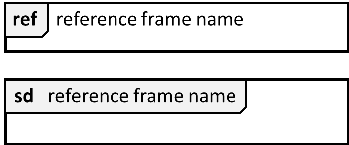
Can interpret sequence diagrams with reference frames

UML uses ref frame to allow a segment of the interaction to be omitted and shown as a separate sequence diagram. Reference frames help you to break complicated sequence diagrams into multiple parts or simply to omit details you are not interested in showing.

Notation:

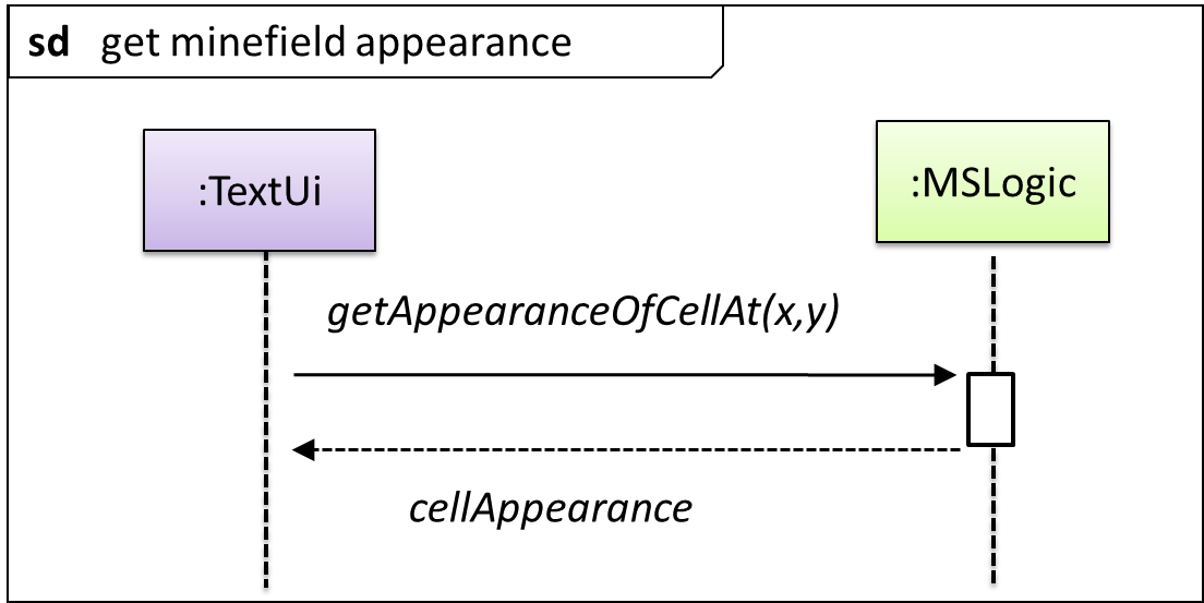
The details of the get minefield appearance interactions have been omitted from the diagram.

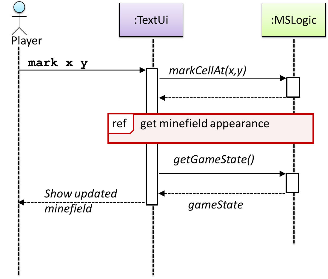
Those details are shown in a separate sequence diagram given below.


W8.3d

Tools → UML → Sequence Diagrams → Parallel paths

Can interpret sequence diagrams with parallel paths

UML uses par frames to indicate parallel paths.

Notation:

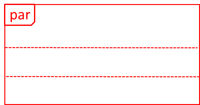
Logic is calling methods CloudServer#poll() and LocalData#poll() in parallel.

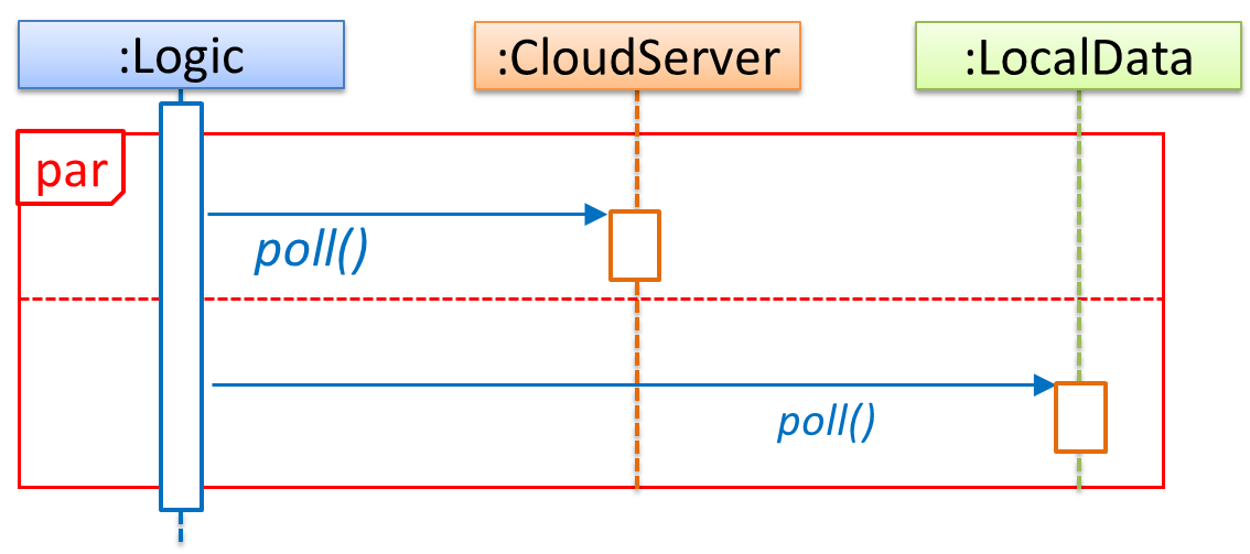
If you show parallel paths in a sequence diagram, the corresponding Java implementation is likely to be multi-threaded because a normal Java program cannot do multiple things at the same time.


Guidance for the item(s) below:

You've already been doing some testing in your project work. It turns out there are many ways to categorize testing. Let's learn some of the more common categorizations of testing.

[W8.4] Testing: Types


Integration Testing

W8.4a

Quality Assurance → Testing → Integration Testing → What

Video

Quality Assurance → Testing → Unit Testing → What →


Can explain integration testing

Integration testing : testing whether different parts of the software work together (i.e. integrates) as expected. Integration tests aim to discover bugs in the 'glue code' related to how components interact with each other. These bugs are often the result of misunderstanding what the parts are supposed to do vs what the parts are actually doing.

Suppose a class Car uses classes Engine and Wheel. If the Car class assumed a Wheel can support a speed of up to 200 mph but the actual Wheel can only support a speed of up to 150 mph, it is the integration test that is supposed to uncover this discrepancy.


W8.4b

Quality Assurance → Testing → Integration Testing → How

Video

Quality Assurance → Testing → Integration Testing → What →


Can use integration testing

Integration testing is not simply a case of repeating the unit test cases using the actual dependencies (instead of the stubs used in unit testing). Instead, integration tests are additional test cases that focus on the interactions between the parts.

Suppose a class Car uses classes Engine and Wheel. Here is how you would go about doing pure integration tests:

a) First, unit test Engine and Wheel.
b) Next, unit test Car in isolation of Engine and Wheel, using stubs for Engine and Wheel.
c) After that, do an integration test for Car by using it together with the Engine and Wheel classes to ensure that Car integrates properly with the Engine and the Wheel.

In practice, developers often use a hybrid of unit+integration tests to minimize the need for stubs.

Here's how a hybrid unit+integration approach could be applied to the same example used above:

(a) First, unit test Engine and Wheel.
(b) Next, unit test Car in isolation of Engine and Wheel, using stubs for Engine and Wheel.
(c) After that, do an integration test for Car by using it together with the Engine and Wheel classes to ensure that Car integrates properly with the Engine and the Wheel. This step should include test cases that are meant to unit test Car (i.e. test cases used in the step (b) of the example above) as well as test cases that are meant to test the integration of Car with Wheel and Engine (i.e. pure integration test cases used of the step (c) in the example above).

Note that you no longer need stubs for Engine and Wheel. The downside is that Car is never tested in isolation of its dependencies. Given that its dependencies are already unit tested, the risk of bugs in Engine and Wheel affecting the testing of Car can be considered minimal.


System Testing

W8.4c

Quality Assurance → Testing → System Testing → What

Can explain system testing

System testing: take the whole system and test it against the system specification.

System testing is typically done by a testing team (also called a QA team).

System test cases are based on the specified external behavior of the system. Sometimes, system tests go beyond the bounds defined in the specification. This is useful when testing that the system fails 'gracefully' when pushed beyond its limits.

Suppose the SUT is a browser that is supposedly capable of handling web pages containing up to 5000 characters. Given below is a test case to test if the SUT fails gracefully if pushed beyond its limits.

Test case: load a web page that is too big
* Input: loads a web page containing more than 5000 characters.
* Expected behavior: aborts the loading of the page
  and shows a meaningful error message.

This test case would fail if the browser attempted to load the large file anyway and crashed.

System testing includes testing against non-functional requirements too. Here are some examples:

  • Performance testing – to ensure the system responds quickly.
  • Load testing (also called stress testing or scalability testing) – to ensure the system can work under heavy load.
  • Security testing – to test how secure the system is.
  • Compatibility testing, interoperability testing – to check whether the system can work with other systems.
  • Usability testing – to test how easy it is to use the system.
  • Portability testing – to test whether the system works on different platforms.

W8.4d

Quality Assurance → Testing → Test Automation → Automated testing of GUIs

Video

Can explain automated GUI testing

If a software product has a GUI (Graphical User Interface) component, all product-level testing (i.e. the types of testing mentioned above) need to be done using the GUI. However, testing the GUI is much harder than testing the CLI (Command Line Interface) or API, for the following reasons:

  • Most GUIs can support a large number of different operations, many of which can be performed in any arbitrary order.
  • GUI operations are more difficult to automate than API testing. Reliably automating GUI operations and automatically verifying whether the GUI behaves as expected is harder than calling an operation and comparing its return value with an expected value. Therefore, automated regression testing of GUIs is rather difficult.
  • The appearance of a GUI (and sometimes even behavior) can be different across platforms and even environments. For example, a GUI can behave differently based on whether it is minimized or maximized, in focus or out of focus, and in a high resolution display or a low resolution display.

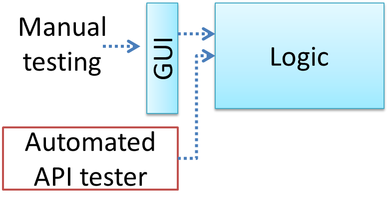
Moving as much logic as possible out of the GUI can make GUI testing easier. That way, you can bypass the GUI to test the rest of the system using automated API testing. While this still requires the GUI to be tested, the number of such test cases can be reduced as most of the system will have been tested using automated API testing.

There are testing tools that can automate GUI testing.

Some tools used for automated GUI testing:

  • TestFX can do automated testing of JavaFX GUIs

  • Visual Studio supports the ‘record replay’ type of GUI test automation.

  • Selenium can be used to automate testing of web application UIs

    Demo video of automated testing of a web application


Exercises


Acceptance Testing

W8.4e

Quality Assurance → Testing → Acceptance Testing → What

Can explain acceptance testing

Acceptance testing (aka User Acceptance Testing (UAT): test the system to ensure it meets the user requirements.

Acceptance tests give an assurance to the customer that the system does what it is intended to do. Acceptance test cases are often defined at the beginning of the project, usually based on the use case specification. Successful completion of UAT is often a prerequisite to the project sign-off.


W8.4f

Quality Assurance → Testing → Acceptance Testing → Acceptance versus system testing

Video Q+

Can explain the differences between system testing and acceptance testing

Acceptance testing comes after system testing. Similar to system testing, acceptance testing involves testing the whole system.

Some differences between system testing and acceptance testing:

System Testing Acceptance Testing
Done against the system specification Done against the requirements specification
Done by testers of the project team Done by a team that represents the customer
Done on the development environment or a test bed Done on the deployment site or on a close simulation of the deployment site
Both negative and positive test cases More focus on positive test cases

Note: negative test cases: cases where the SUT is not expected to work normally e.g. incorrect inputs; positive test cases: cases where the SUT is expected to work normally

Requirement specification versus system specification

The requirement specification need not be the same as the system specification. Some example differences:

Requirements specification System specification
limited to how the system behaves in normal working conditions can also include details on how it will fail gracefully when pushed beyond limits, how to recover, etc. specification
written in terms of problems that need to be solved (e.g. provide a method to locate an email quickly) written in terms of how the system solves those problems (e.g. explain the email search feature)
specifies the interface available for intended end-users could contain additional APIs not available for end-users (for the use of developers/testers)

However, in many cases one document serves as both a requirement specification and a system specification.

Passing system tests does not necessarily mean passing acceptance testing. Some examples:

  • The system might work on the testbed environments but might not work the same way in the deployment environment, due to subtle differences between the two environments.
  • The system might conform to the system specification but could fail to solve the problem it was supposed to solve for the user, due to flaws in the system design.

Exercises


Alpha/Beta Testing

W8.4g

Quality Assurance → Testing → Alpha/Beta Testing → What

Can explain alpha and beta testing

Alpha testing is performed by the users, under controlled conditions set by the software development team.

Beta testing is performed by a selected subset of target users of the system in their natural work setting.

An open beta release is the release of not-yet-production-quality-but-almost-there software to the general population. For example, Google’s Gmail was in 'beta' for many years before the label was finally removed.


Exploratory vs Scripted Testing

W8.4h

Quality Assurance → Testing → Exploratory and Scripted Testing → What

Can explain exploratory testing and scripted testing

Here are two alternative approaches to testing a software: Scripted testing and Exploratory testing.

  1. Scripted testing: First write a set of test cases based on the expected behavior of the SUT, and then perform testing based on that set of test cases.

  2. Exploratory testing: Devise test cases on-the-fly, creating new test cases based on the results of the past test cases.

Exploratory testing is ‘the simultaneous learning, test design, and test execution’ [source: bach-et-explained] whereby the nature of the follow-up test case is decided based on the behavior of the previous test cases. In other words, running the system and trying out various operations. It is called exploratory testing because testing is driven by observations during testing. Exploratory testing usually starts with areas identified as error-prone, based on the tester’s past experience with similar systems. One tends to conduct more tests for those operations where more faults are found.

Here is an example thought process behind a segment of an exploratory testing session:

“Hmm... looks like feature x is broken. This usually means feature n and k could be broken too; you need to look at them soon. But before that, you should give a good test run to feature y because users can still use the product if feature y works, even if x doesn’t work. Now, if feature y doesn’t work 100%, you have a major problem and this has to be made known to the development team sooner rather than later...”

Exploratory testing is also known as reactive testing, error guessing technique, attack-based testing, and bug hunting.

Exercises


W8.4i

Quality Assurance → Testing → Exploratory and Scripted Testing → When

Video

Can explain the choice between exploratory testing and scripted testing

Which approach is better – scripted or exploratory? A mix is better.

The success of exploratory testing depends on the tester’s prior experience and intuition. Exploratory testing should be done by experienced testers, using a clear strategy/plan/framework. Ad-hoc exploratory testing by unskilled or inexperienced testers without a clear strategy is not recommended for real-world non-trivial systems. While exploratory testing may allow us to detect some problems in a relatively short time, it is not prudent to use exploratory testing as the sole means of testing a critical system.

Scripted testing is more systematic, and hence, likely to discover more bugs given sufficient time, while exploratory testing would aid in quick error discovery, especially if the tester has a lot of experience in testing similar systems.

In some contexts, you will achieve your testing mission better through a more scripted approach; in other contexts, your mission will benefit more from the ability to create and improve tests as you execute them. I find that most situations benefit from a mix of scripted and exploratory approaches. --[source: bach-et-explained]

Exercises


Guidance for the item(s) below:

One of the primary goals of a software engineer is to avoid bugs. You certainly don't want to be the person responsible for causing a major bug that caused heavy damages to some party. That's why we need to focus heavily on testing -- one of the main defences against bugs.

The next few sections cover some intermediate level testing topics that you are very likely to encounter in software engineering.

[W8.5] Testing: Intermediate Concepts


Dependency Injection

Video

W8.5a

Quality Assurance → Testing → Dependency Injection → What

Can explain dependency injection

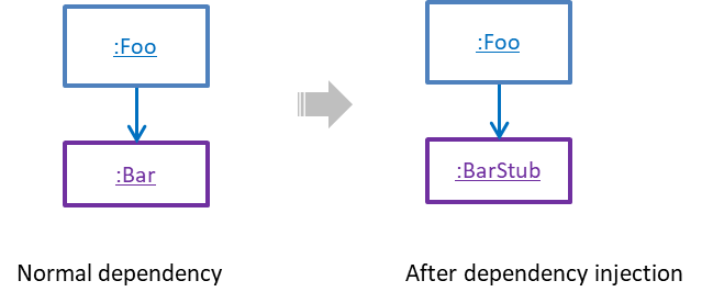
Dependency injection is the process of 'injecting' objects to replace current dependencies with a different object. This is often used to inject stubs to isolate the from its so that it can be tested in isolation.

A Foo object normally depends on a Bar object, but you can inject a BarStub object so that the Foo object no longer depends on a Bar object. Now you can test the Foo object in isolation from the Bar object.


W8.5b : OPTIONAL

Quality Assurance → Testing → Dependency Injection → How


Testability

W8.5c

Quality Assurance → Testing → Introduction → Testability

Can explain testability

Testability is an indication of how easy it is to test an SUT. As testability depends a lot on the design and implementation, you should try to increase the testability when you design and implement software. The higher the testability, the easier it is to achieve better quality software.


Test Coverage

Video

W8.5d

Quality Assurance → Testing → Test Coverage → What

Can explain test coverage

Test coverage is a metric used to measure the extent to which testing exercises the code i.e., how much of the code is 'covered' by the tests.

Here are some examples of different coverage criteria:

  • Function/method coverage : based on functions executed e.g., testing executed 90 out of 100 functions.
  • Statement coverage : based on the number of lines of code executed e.g., testing executed 23k out of 25k LOC.
  • Decision/branch coverage : based on the decision points exercised e.g., an if statement evaluated to both true and false with separate test cases during testing is considered 'covered'.
  • Condition coverage : based on the boolean sub-expressions, each evaluated to both true and false with different test cases. Condition coverage is not the same as the decision coverage.

if(x > 2 && x < 44) is considered one decision point but two conditions.

For 100% branch or decision coverage, two test cases are required:

  • (x > 2 && x < 44) == true : [e.g. x == 4]
  • (x > 2 && x < 44) == false : [e.g. x == 100]

For 100% condition coverage, three test cases are required:

  • (x > 2) == true , (x < 44) == true : [e.g. x == 4] [see note 1]
  • (x < 44) == false : [e.g. x == 100]
  • (x > 2) == false : [e.g. x == 0]

Note 1: A case where both conditions are true is needed because most execution environments use a short circuiting behavior for compound boolean expressions e.g., given an expression c1 && c2, c2 will not be evaluated if c1 is false (as the final result is going to be false anyway).

  • Path coverage measures coverage in terms of possible paths through a given part of the code executed. 100% path coverage means all possible paths have been executed. A commonly used notation for path analysis is called the Control Flow Graph (CFG).
  • Entry/exit coverage measures coverage in terms of possible calls to and exits from the operations in the SUT.

Exercises


W8.5e

Quality Assurance → Testing → Test Coverage → How

Can explain how test coverage works

Measuring coverage is often done using coverage analysis tools. Most IDEs have inbuilt support for measuring test coverage, or at least have plugins that can measure test coverage.

Coverage analysis can be useful in improving the quality of testing e.g., if a set of test cases does not achieve 100% branch coverage, more test cases can be added to cover missed branches.

Measuring code coverage in Intellij IDEA (watch from 4 minutes 50 seconds mark)


TDD

Video

W8.5f

Quality Assurance → Testing → Test-Driven Development → What

Can explain TDD

Test-Driven Development(TDD) advocates writing the tests before writing the SUT, while evolving functionality and tests in small increments. In TDD you first define the precise behavior of the SUT using test code, and then update the SUT to match the specified behavior. While TDD has its fair share of detractors, there are many who consider it a good way to reduce defects. One big advantage of TDD is that it guarantees the code is testable.

Exercises


W8.5g : OPTIONAL

Quality Assurance → Testing → Test-Driven Development → How


Follow up notes for the item(s) above:

You are welcome to, but not required to, follow the TDD approach in your project.