Week 4 [Fri, Jan 27th] - Topics
Detailed Table of Contents
Guidance for the item(s) below:
In the tP, you'll be thrown into a codebase of about 6K . It would be hard to understand the design simply by reading the code. That's why the code base comes with a Developer Guide containing some design models i.e., the diagrams. That means, you should be able to interpret those models by the time you start the tP in a few weeks. 😨
Let's start getting ready for that today. First, let's go through a high-level explanation of models.
Can explain models
A model is a representation of something else.
A class diagram is a model that represents a software design.
A model provides a simpler view of a complex entity because a model captures only a selected aspect. This omission of some aspects implies models are abstractions.
A class diagram captures the structure of the software design but not the behavior.
Multiple models of the same entity may be needed to capture it fully.
In addition to a class diagram (or even multiple class diagrams), a number of other diagrams may be needed to capture various interesting aspects of the software.
Can explain how models are used
In software development, models are useful in several ways:
a) To analyze a complex entity related to software development.
Some examples of using models for analysis:
- Models of the can be built to aid the understanding of the problem to be solved.
- When planning a software solution, models can be created to figure out how the solution is to be built. An architecture diagram is such a model.
b) To communicate information among stakeholders. Models can be used as a visual aid in discussions and documentation.
Some examples of using models to communicate:
- You can use an architecture diagram to explain the high-level design of the software to developers.
- A business analyst can use a use case diagram to explain to the customer the functionality of the system.
- A class diagram can be reverse-engineered from code so as to help explain the design of a component to a new developer.
c) As a blueprint for creating software. Models can be used as instructions for building software.
Some examples of using models as blueprints:
- A senior developer draws a class diagram to propose a design for an OOP software and passes it to a junior programmer to implement.
- A software tool allows users to draw UML models using its interface and the tool automatically generates the code based on the model.
Exercises
Can identify UML models
The following diagram uses the class diagram notation to show the different types of UML diagrams.
source:https://en.wikipedia.org/
Guidance for the item(s) below:
Now that we have a high-level understanding of the role played by models, let's start learning some UML models, starting with UML class diagrams (and object diagrams which are like a distant cousin of class diagrams).
Note that we are learning to interpret these models only, not draw them (that would come later), or design them. Hence, we will be going through these topics fairly rapidly.
Design → OOP → Classes → Basic
Can explain structure modeling of OO solutions
An OO solution is basically a network of objects interacting with each other. Therefore, it is useful to be able to model how the relevant objects are 'networked' together inside a software i.e. how the objects are connected together.
Given below is an illustration of some objects and how they are connected together. Note: the diagram uses an ad-hoc notation.

Note that these object structures within the same software can change over time.
Given below is how the object structure in the previous example could have looked like at a different time.

However, object structures do not change at random; they change based on a set of rules, as was decided by the designer of that software. Those rules that object structures need to follow can be illustrated as a class structure i.e. a structure that exists among the relevant classes.
Here is a class structure (drawn using an ad-hoc notation) that matches the object structures given in the previous two examples. For example, note how this class structure does not allow any connection between Genre objects and Author objects, a rule followed by the two object structures above.

UML Object Diagrams are used to model object structures and UML Class Diagrams are used to model class structures of an OO solution.
Here is an object diagram for the above example:

And here is the class diagram for it:

Can use basic-level class diagrams
Contents of the panels given below belong to a different chapter; they have been embedded here for convenience and are collapsed by default to avoid content duplication in the printed version.
UML Class Diagrams → Introduction → What
Classes form the basis of class diagrams.
UML Class Diagrams → Classes → What
UML Class Diagrams → Class-Level Members → What
Associations are the main connections among the classes in a class diagram.
OOP Associations → What
UML Class Diagrams → Associations → What
The most basic class diagram is a bunch of classes with some solid lines among them to represent associations, such as this one.
An example class diagram showing associations between classes.

In addition, associations can show additional decorations such as association labels, association roles, multiplicity and navigability to add more information to a class diagram.
UML Class Diagrams → Associations → Labels
UML Class Diagrams → Associations → Roles
OOP Associations → Multiplicity
UML Class Diagrams → Associations → Multiplicity
OOP Associations → Navigability
UML Class Diagrams → Associations → Navigability
Here is the same class diagram shown earlier but with some additional information included:

Exercises
Which association notations are shown?
Explain Class Diagram
Draw Class Diagram for Box etc.
Can use basic object diagrams
UML → Object Diagrams → Introduction
Object diagrams can be used to complement class diagrams. For example, you can use object diagrams to model different object structures that can result from a design represented by a given class diagram.
UML → Object Diagrams → Objects
UML → Object Diagrams → Associations
Exercises
Draw an Object Diagram for Box etc.
Can distinguish between class diagrams and object diagrams
Compared to the notation for class diagrams, object diagrams differ in the following ways:
- Show objects instead of classes:
- Instance name may be shown
- There is a
:before the class name - Instance and class names are underlined
- Methods are omitted
- Multiplicities are omitted. Reason: an association line in an object diagram represents a connection to exactly one object (i.e., the multiplicity is always 1).
Furthermore, multiple object diagrams can correspond to a single class diagram.
Both object diagrams are derived from the same class diagram shown earlier. In other words, each of these object diagrams shows ‘an instance of’ the same class diagram.
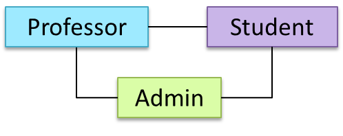

When the class diagram has an inheritance relationship, the object diagram should show either an object of the parent class or the child class, but not both.
Suppose Employee is a child class of the Person class. The class diagram will be as follows:

Now, how do you show an Employee object named jake?
 This is not correct, as there should be only one object.
 This is OK.
 This is OK, as
 jakeis aPersontoo. That is, we can show the parent class instead of the child class if the child class doesn't matter to the purpose of the diagram (i.e., the reader of this diagram will not need to know thatjakeis in fact anEmployee).
Association labels/roles can be omitted unless they add value (e.g., showing them is useful if there are multiple associations between the two classes in concern -- otherwise you wouldn't know which association the object diagram is showing)
Consider this class diagram and the object diagram:
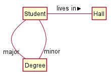
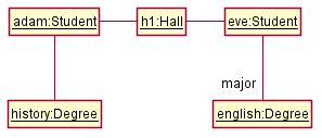
We can clearly see that both Adam and Eve lives in hall h1 (i.e., OK to omit the association label lives in) but we can't see if History is Adam's major or his minor (i.e., the diagram should have included either an association label or a role there). In contrast, we can see Eve is an English major.
Exercises
Can show an association as an attribute
An association can be shown as an attribute instead of a line.
Association multiplicities and the default value can be shown as part of the attribute using the following notation. Both are optional.
name: type [multiplicity] = default value
The diagram below depicts a multi-player Square Game being played on a board comprising of 100 squares. Each of the squares may be occupied with any number of pieces, each belonging to a certain player.
A Piece may or may not be on a Square. Note how that association can be replaced by an isOn attribute of the Piece class. The isOn attribute can either be null or hold a reference to a Square object, matching the 0..1 multiplicity of the association it replaces. The default value is null.
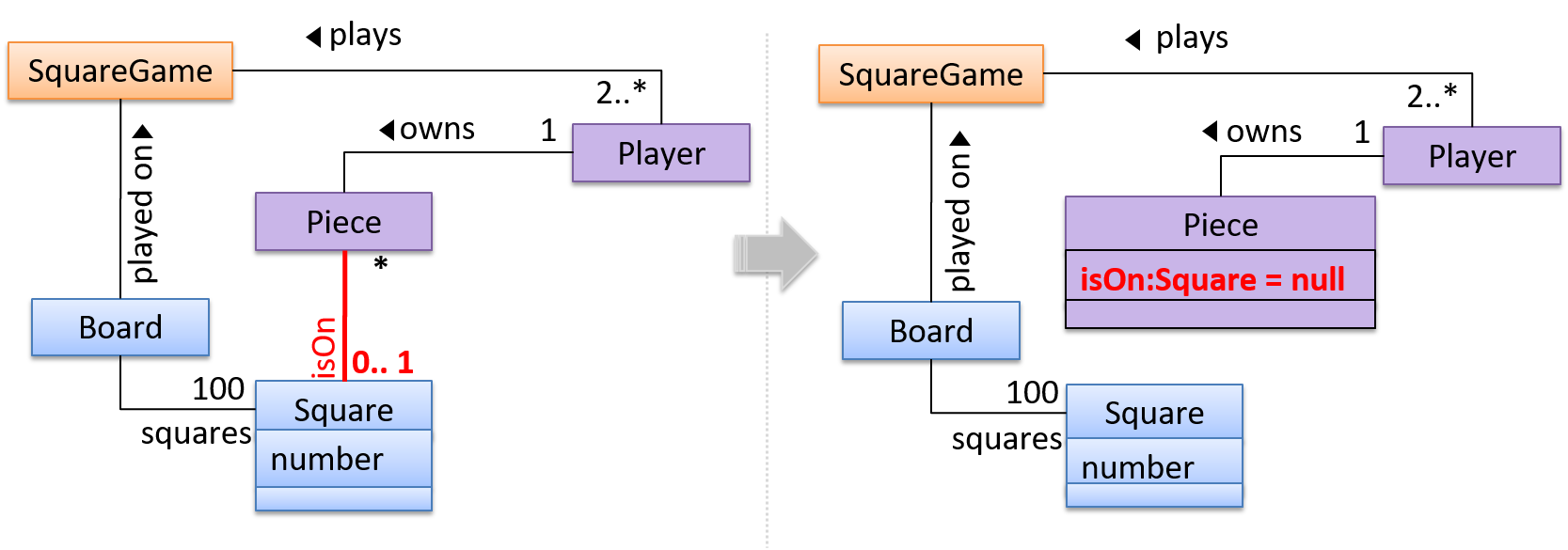
The association that a Board has 100 Squares can be shown in either of these two ways:

Show each association as either an attribute or a line but not both. A line is preferred as it is easier to spot.
Design → Modeling → Class Diagrams (Basic)
Can use intermediate-level class diagrams
A class diagram can also show different types of relationships between classes: inheritance, compositions, aggregations, dependencies.
Modeling inheritance
OOP → Inheritance → What
UML → Class Diagrams → Inheritance → What
Modeling composition
OOP → Associations → Composition
UML → Class Diagrams → Composition → What
Modeling aggregation
OOP → Associations → Aggregation
UML → Class Diagrams → Aggregation → What
Modeling dependencies
OOP → Associations → Dependencies
UML → Class Diagrams → Dependencies → What
A class diagram can also show different types of class-like entities:
Exercises
Statements about class diagram
Explain notations in the class diagram
Draw a Class Diagram for the code (StockItem, Inventory, Review, etc.)
Can explain the meaning of association classes
An association class represents additional information about an association. It is a normal class but plays a special role from a design point of view.
A Man class and a Woman class are linked with a ‘married to’ association and there is a need to store the date of marriage. However, that data is related to the association rather than specifically owned by either the Man object or the Woman object. In such situations, an additional association class can be introduced, e.g. a Marriage class, to store such information.
Implementing association classes
There is no special way to implement an association class. It can be implemented as a normal class that has variables to represent the endpoint of the association it represents.
In the code below, the Transaction class is an association class that represents a transaction between a Person who is the seller and another Person who is the buyer.
class Transaction {

    //all fields are compulsory
    Person seller;
    Person buyer;
    Date date;
    String receiptNumber;

    Transaction(Person seller, Person buyer, Date date, String receiptNumber) {
        //set fields
    }
}
Exercises
Guidance for the item(s) below:
Switching to Java now, let's learn how to write Java GUIs. Fair warning: GUI programming is hard in any language, especially so in Java. Buckle down and get through it; there's no way around it.
Can use JavaFX to build a simple GUI
JavaFX is a technology for building Java-based GUIs. Previously it was a part Java itself, but has become a third-party dependency since then. It is now being maintained by OpenJDK.
Refer to the JavaFX tutorial @SE-EDU/guides to learn how to get started with JavaFX.
Guidance for the item(s) below:
While we are on the topic of Java, also take note of this is a lesser-known Java 'syntactic sugar' feature that was introduced not long ago, in case you come across it one day or find some use for it in your coding.
Can use Java varargs feature
Variable Arguments (Varargs) is a syntactic sugar type feature that allows writing a method that can take a variable number of arguments.
The search method below can be called as search(), search("book"), search("book", "paper"), etc.
public static void search(String ... keywords){
   // method body
}
Resources:
Can explain the need for good names in code
Proper naming improves the readability of code. It also reduces bugs caused by ambiguities regarding the intent of a variable or a method.
There are only two hard things in Computer Science: cache invalidation and naming things. -- Phil Karlton
Can improve code quality using technique: use nouns for things and verbs for actions
Every system is built from a domain-specific language designed by the programmers to describe that system. Functions are the verbs of that language, and classes are the nouns.
-- Robert C. Martin, Clean Code: A Handbook of Agile Software Craftsmanship
Use nouns for classes/variables and verbs for methods/functions.
Examples:
| Name for a | Bad | Good |
|---|---|---|
| Class | CheckLimit | LimitChecker |
| Method | result() | calculate() |
Distinguish clearly between single-valued and multi-valued variables.
Examples:
Good
Person student;
ArrayList<Person> students;
Good
name = 'Jim'
names = ['Jim', 'Alice']
Can improve code quality using technique: use standard words
Use correct spelling in names. Avoid 'texting-style' spelling. Avoid foreign language words, slang, and names that are only meaningful within specific contexts/times e.g. terms from private jokes, a TV show currently popular in your country.
Can improve code quality using technique: use name to explain
A name is not just for differentiation; it should explain the named entity to the reader accurately and at a sufficient level of detail.
Examples:
| Bad | Good |
|---|---|
processInput() (what 'process'?) | removeWhiteSpaceFromInput() |
flag | isValidInput |
temp |
If a name has multiple words, they should be in a sensible order.
Examples:
| Bad | Good |
|---|---|
bySizeOrder() | orderBySize() |
Imagine going to the doctor's and saying "My eye1 is swollen"! Don’t use numbers or case to distinguish names.
Examples:
| Bad | Bad | Good |
|---|---|---|
value1, value2 | value, Value | originalValue, finalValue |
Can improve code quality using technique: not too long, not too short
While it is preferable not to have lengthy names, names that are 'too short' are even worse. If you must abbreviate or use acronyms, do it consistently. Explain their full meaning at an obvious location.
Can improve code quality using technique: avoid misleading names
Related things should be named similarly, while unrelated things should NOT.
Example: Consider these variables
colorBlack: hex value for color blackcolorWhite: hex value for color whitecolorBlue: number of times blue is usedhexForRed: hex value for color red
This is misleading because colorBlue is named similar to colorWhite and colorBlack but has a different purpose while hexForRed is named differently but has a very similar purpose to the first two variables. The following is better:
hexForBlackhexForWhitehexForRedblueColorCount
Avoid misleading or ambiguous names (e.g. those with multiple meanings), similar sounding names, hard-to-pronounce ones (e.g. avoid ambiguities like "is that a lowercase L, capital I or number 1?", or "is that number 0 or letter O?"), almost similar names.
Examples:
| Bad | Good | Reason |
|---|---|---|
phase0 | phaseZero | Is that zero or letter O? |
rwrLgtDirn | rowerLegitDirection | Hard to pronounce |
right left wrong | rightDirection leftDirection wrongResponse | right is for 'correct' or 'opposite of 'left'? |
redBooks readBooks | redColorBooks booksRead | red and read (past tense) sounds the same |
FiletMignon | egg | If the requirement is just a name of a food, egg is a much easier to type/say choice than FiletMignon |
Can explain static analysis
Static analysis: Static analysis is the analysis of code without actually executing the code.
Static analysis of code can find useful information such as unused variables, unhandled exceptions, style errors, and statistics. Most modern IDEs come with some inbuilt static analysis capabilities. For example, an IDE can highlight unused variables as you type the code into the editor.
The term static in static analysis refers to the fact that the code is analyzed without executing the code. In contrast, dynamic analysis requires the code to be executed to gather additional information about the code e.g., performance characteristics.
Higher-end static analysis tools (static analyzers) can perform more complex analysis such as locating potential bugs, memory leaks, inefficient code structures, etc.
Some example static analyzers for Java: CheckStyle, PMD, FindBugs
Linters are a subset of static analyzers that specifically aim to locate areas where the code can be made 'cleaner'.
Guidance for the item(s) below:
Next up are two techniques that can be used to improve code quality. You need to learn them as you will be encountering both in your iP soon.
Can explain code reviews
Code review is the systematic examination of code with the intention of finding where the code can be improved.
Reviews can be done in various forms. Some examples below:
Pull Request reviews
- Project Management Platforms such as GitHub and BitBucket allow the new code to be proposed as Pull Requests and provide the ability for others to review the code in the PR.
In pair programming
- As pair programming involves two programmers working on the same code at the same time, there is an implicit review of the code by the other member of the pair.
Formal inspections
Inspections involve a group of people systematically examining project artifacts to discover defects. Members of the inspection team play various roles during the process, such as:
- the author - the creator of the artifact
- the moderator - the planner and executor of the inspection meeting
- the secretary - the recorder of the findings of the inspection
- the inspector/reviewer - the one who inspects/reviews the artifact
Advantages of code review over testing:
- It can detect functionality defects as well as other problems such as coding standard violations.
- It can verify non-code artifacts and incomplete code.
- It does not require test drivers or stubs.
Disadvantages:
- It is a manual process and therefore, error prone.
Resources
- 10 tips for reviewing code you don’t like - a blog post by David Lloyd (a Red Hat developer).
Can review PRs on GitHub
The PR review stage is a dialog between the PR author and members of the repo that received the PR, in order to refine and eventually merge the PR.
Given below are some steps you can follow when reviewing a PR.
1. Locate the PR:
- Go to the GitHub page of the repo.
- Click on the Pull requests tab.
- Click on the PR you want to review.
2. Read the PR description. It might contain information relevant to reviewing the PR.
3. Click on the Files changed tab to see the diff view.
4. Add review comments:
- Hover over the line you want to comment on and click on the icon that appears on the left margin. That should create a text box for you to enter your comment.
- To give a comment related to multiple lines, click-and-drag the icon. The result will look like this:

- To give a comment related to multiple lines, click-and-drag the icon. The result will look like this:
- Enter your comment.
- This page @SE-EDU/guides has some best practices PR reviewers can follow.
- To suggest an in-line code change, click on this icon:
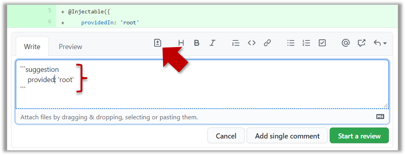
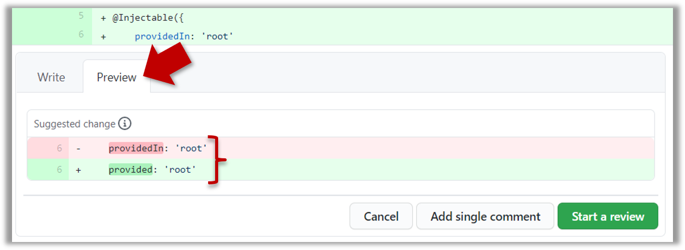
The comment will look like this to the viewers:
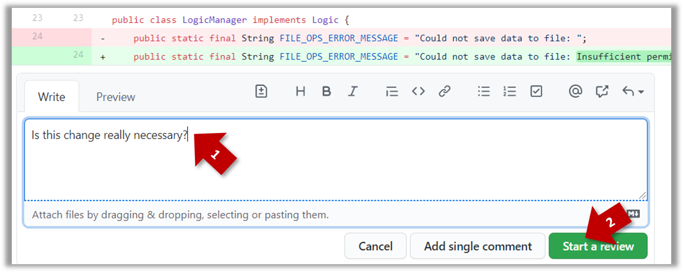
- After typing in the comment, click on the Start a review button (not the Add single comment button. This way, your comment is saved but not visible to others yet. It will be visible to others only when you have finished the entire review.
- Repeat the above steps to add more comments.
5. Submit the review:
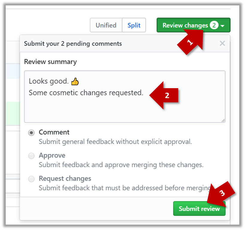
- When there are no more comments to add, click on the Review changes button (on the top right of the diff page).
- Type in an overall comment about the PR, if any. e.g.,
Overall, I found your code easy to read for the most part except a few places where the nesting was too deep. I noted a few minor coding standard violations too. Some of the classes are getting quite long. Consider splitting into smaller classes if that makes sense.LGTMis often used in such overall comments, to indicateLooks good to me.
nit(as in nit picking) is another such term, used to indicate minor flaws e.g.,LGTM. Just a few nits to fix.. - Choose
Approve,Comment, orRequest changesoption as appropriate and click on the Submit review button.
